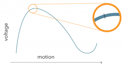
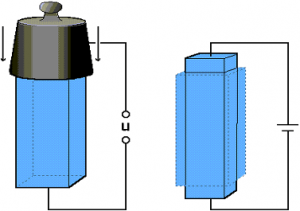
The word piezo is derived from the Greek word for pressure. In 1880 Jacques and Pierre Curie discovered that pressure generates electrical charges in several crystals such as quartz and tourmaline; they called this phenomenon the piezoelectric effect. Later they noticed that electrical fields can deform piezoelectric materials. This effect is called the inverse piezoelectric effect.
THE PIEZO MOTOR TECHNOLOGY
The piezoelectric effect
Advantages of the Piezo LEGS Technology
High precision
Piezo LEGS® can easily position on a sub-micron level, or even down to sub-nanometers. The resolution depends on the electronics; the limiting factor is not the motor itself. With the possibility to microstep down to sub-nanometer, you can achieve a truly smooth motion.
No backlash
A controlled linear motion without backlash is accomplished without the need of gearboxes or ball screws – the motor responds instantly. The true direct drive enables a combination of high precision and a dynamic speed range. Piezo LEGS® is self-locking and will hold load even when powered off.
By applying voltage to a piezoelectric material, you can make it change its shape. Through the clever design of the Piezo LEGS® ceramic actuators, each of the motor “legs” can be elongated as well as bent sideways. With appropriate drive signals, you can create synchronized movement of each pair of its four legs, and it will begin to walk just like an animal would – step by step, and stopping at any instance on a nanometer level. The direct friction coupling between legs and drive rod means Piezo LEGS® will operate without the slightest backlash or mechanical play. The direct drive also gives full force, power-off locking without any power consumption.
Non-magnetic
The drive unit in the Piezo LEGS® is non-magnetic. This enables motor designs suitable for high-magnetic environments or where magnetic disturbance is an issue.
Piezo LEGS® motors don’t have the windings of a DC motor and will not be a source of magnetic flux. Standard housing material is stainless steel, so the body of the motor will be ferritic by nature and will disturb an external magnetic field. Completely non-magnetic motors are also available, where motor housing and other parts are made from non-magnetic alloys. Motors of that kind will be compatible to use even inside an MRI machine without disturbing the image.
Non-magnetic motors have a magnetic flux density of less than 1 nT (sensor sensitivity in reference measurements) at a distance of 10 mm from the motor housing.
Compact designs
The motor has a compact design which fits perfectly in OEM applications.
PiezoMotor makes high-precision motors with direct drive. There’s no need for gears or mechanical transmissions. The result is backlash-free linear motion with nanometer or even sub-nanometer resolution. Reducing the number of parts also means that the size of the motor can be decreased considerably compared with traditional solutions. Simple drive electronics also save space. Any application driven with a Piezo LEGS® motor can be miniaturized to a high degree.
Using miniaturized Piezo LEGS® motors from PiezoMotor is beneficial for plenty of other reasons as well – increased resolution, instant response, no backlash and no power draw when motionless.
As well as reducing complexity to decrease motor dimensions, miniaturization also means size reductions for manufacturers. Scaling down integrated circuits, for example, puts a greater demand on precision in the lithography processes. Piezo LEGS® motors improve accuracy to such an extent that new-generation integrated circuits are even more miniaturized, yet still offer better performance. The semiconductor industry is cutting-edge, just like products from PiezoMotor.
We offer a set of standard motors, but the basic technology can easily be customized. Don’t hesitate to contact our skilled engineering team for advice.
The system
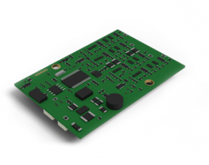
To run a piezo motor you need electronics, as in all modern motion control. The core of the motor is a multi-layer piezo ceramic, a component with high performance at low voltage. By applying controlled electrical voltage to the ceramic, a linear or rotary motion is created.
To keep control of the position, an encoder is required. The resolution of the system depends on both the encoder resolution and the electronics resolution.
One of the greatest advantages of piezo-based systems is the combination of high precision and quick response time without increasing cost of the system.
A piezo motor-based system has a true direct drive, meaning that the object to be moved is directly connected to the piezoceramic actuator legs in the motor via the drive rod of the motor. This has the important advantage of giving no backlash, quick response time, and high resolution. This enables short cycle times in repeated move-and-settle applications reducing overall processing time.
Controller
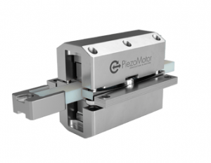
Motor with drive rod
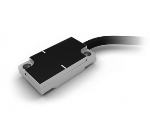
Encoder
The motor
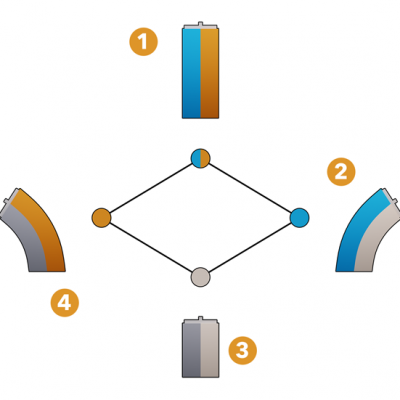
Piezo LEGS® work with friction drive, where force is created by the internal preload of the piezoceramic actuator legs in direct friction contact with the rotor or drive rod. When the legs start walking, they are always in mechanical contact with the drive rod.
1
Voltage is applied to both left and right, causing the leg to extend to its fullest length
2
Voltage is applied to the left part of the leg, causing the leg to extend to the right
3
No voltage applied to the leg
4
Voltage is applied to the right part of the leg, causing the leg to extend to the left




The electronics
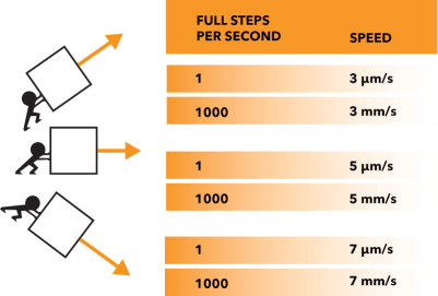
A controlled motion is created by applying voltage signals to the ceramics. The step length depends on the load as shown in the figure below. One full step can be divided into several thousands of microsteps. The length of a microstep reaches down to sub-nanometer level.
Waveform optimized for high microstep resolution
A microstep = a fraction of the waveform (full step); e.g. 8192 microsteps per waveform.
1 microstep, less than 1 nm
